Primary Flight Controls: Understanding Ailerons, Rudder, and Elevator
A Technical Analysis of Primary Flight Controls. Discover how ailerons, rudder, and elevator control an aircraft. A complete technical analysis of aerodynamics and the three axes of rotation in flight.
BLOGRECENTES
1/19/20267 min read
Introduction
To watch a commercial airliner weighing hundreds of tons smoothly rotate off a runway, execute precise turns, and land with delicate grace is to witness a triumph of engineering. To the casual observer, it looks like magic. To the aviation enthusiast and professional, it is the result of a complex interplay between aerodynamics, mechanics, and the pilot's skill in manipulating the forces of nature.
But how, exactly, does a human being command such a vast machine in three-dimensional space? Unlike a car, which moves on only two axes (forward/backward and left/right on the ground), an airplane operates in a fluid environment where it must control its attitude around three axes of rotation simultaneously.
The secret lies not in brute force or massive directional engines, but in the subtle and precise manipulation of the airflow passing over the aircraft's structure. This is where the primary flight controls come in. They are the fundamental movable surfaces—the external tendons and muscles of the plane—that allow the pilot to alter the machine's path, altitude, and balance. Without them, controlled flight would be impossible; the aircraft would be merely an expensive projectile at the mercy of the wind.
In this technical article, we will conduct a detailed "pre-flight inspection" of these vital systems. We will dissect the three main surfaces and their corresponding axes, step into the cockpit to understand the human-machine interface, and finally dive into the aerodynamic physics that makes it all possible.
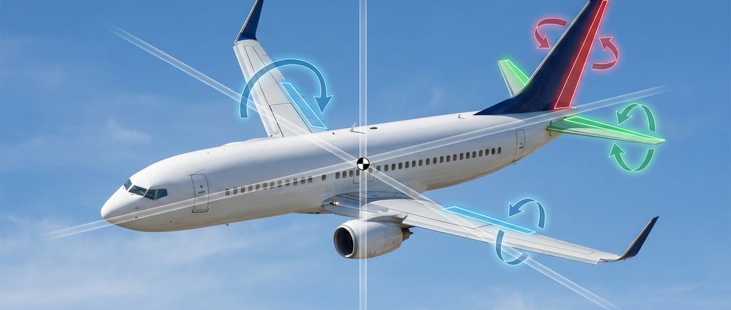
Surfaces and Axes of Rotation
To understand how an airplane moves, we must first define its coordinate system. Imagine an aircraft in flight. The exact point where all its weight is perfectly balanced is called the Center of Gravity (CG). All rotational movements in flight occur around this point, via three imaginary axes that intersect there.
Primary flight controls are specifically designed to generate torque (rotational moment) around these axes.
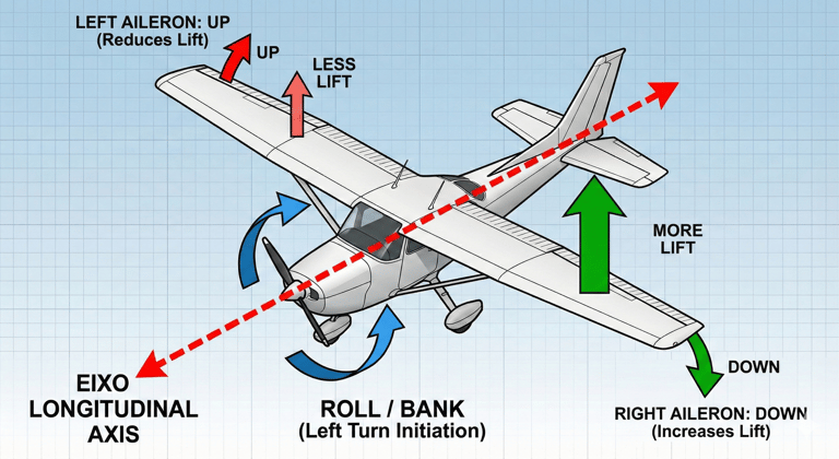
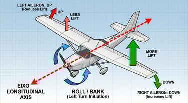
1. The Longitudinal Axis and Ailerons (Roll/Bank Control)
The longitudinal axis runs from the nose to the tail of the aircraft. Rotation around this axis is called roll (or bank). It is the movement that causes one wing to rise and the other to lower, initiating a turn.
The primary control for roll is the ailerons (French for "little wing"). They are located on the trailing edge (the back part) of the wings, usually near the tips, where they have the greatest lever arm to exert force.
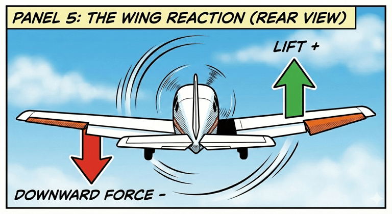
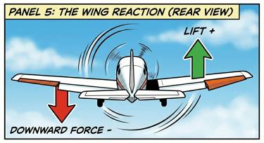
The key characteristic of ailerons is their differential movement. When a pilot wishes to bank left, the left wing's aileron raises, while the right wing's aileron lowers simultaneously. This creates an imbalance in lift forces between the two wings, causing the aircraft to rotate around the longitudinal axis towards the wing with less lift.
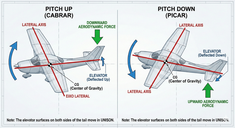
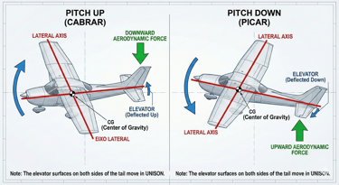
2. The Lateral Axis and the Elevator (Pitch Control)
The lateral axis extends from wingtip to wingtip. Rotation around this axis is called pitch. It is the movement of raising the nose to climb, or lowering the nose to descend.
The primary control for pitch is the elevator. It is situated on the tail of the aircraft, hinged to the trailing edge of the horizontal stabilizer.
Unlike ailerons, elevator surfaces (on both sides of the tail) move in unison. When the elevator moves up, it creates a downward aerodynamic force on the tail. Since the tail is far from the Center of Gravity, this force creates a moment that levers the airplane's nose upwards. The reverse occurs when the elevator moves down, lifting the tail and lowering the nose.
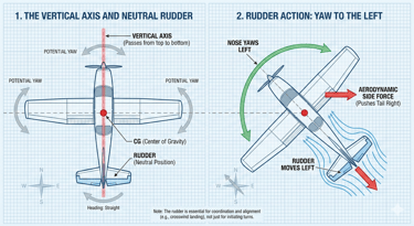
3. The Vertical Axis and the Rudder (Yaw Control)
The vertical axis passes from top to bottom through the center of the aircraft. Rotation around this axis is called yaw. It is the movement of the airplane's nose to the left or right, similar to turning a car's steering wheel, but with different implications in the air.
The primary control for yaw is the rudder. It is the movable surface hinged to the trailing edge of the vertical stabilizer (the tail fin).
Moving the rudder to the left creates a sideways force on the tail that pushes the empennage to the right, consequently swinging the nose to the left. The rudder is crucial not so much for initiating turns (a primary function of ailerons), but for keeping them coordinated, compensating for "adverse yaw," and aligning the aircraft's nose with the runway during crosswind landings.
The Human Interface: From Cockpit to Surfaces
Knowing the external surfaces, the next logical question is: how does the pilot's intention in the cockpit translate into movement on these distant surfaces? The human-machine interface is designed to be intuitive, mimicking natural balance reactions.
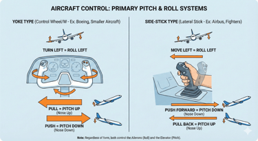
The Yoke or Side-Stick
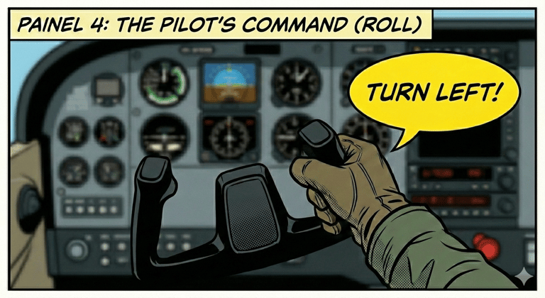
The primary control in the pilot's hands is the control column. In smaller aircraft and many airliners (like Boeing), it looks like a "W" or a steering wheel (called a yoke). In aircraft like modern Airbus and fighters, it is a side-stick or center stick. Regardless of the form, it controls two axes:
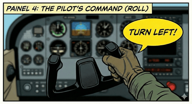
Roll Control (Ailerons): Turning the yoke left or moving the stick left commands a left roll. The mechanical or electronic connection ensures the left aileron moves up and the right moves down.
Pitch Control (Elevator): Pulling the yoke or stick towards the pilot commands nose-up pitch. Pushing it forward commands nose-down pitch.
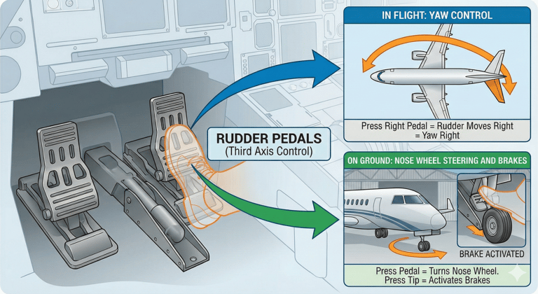
The Rudder Pedals
On the cockpit floor, there are two pedals that control the third axis.
Yaw Control (Rudder): Pressing the right pedal commands a yaw to the right (the rudder on the tail moves right). Pressing the left causes a yaw to the left. It is important to note that on the ground, these same pedals usually control nose wheel steering and the main wheel brakes.
The Evolution of Connection: From Cables to Fly-By-Wire
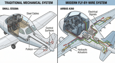
In light and older aircraft, the connection between the yoke/pedals and the surfaces is purely mechanical. A complex network of tensioned steel cables, pulleys, push-rods, and bellcranks transmits the pilot's muscle power directly to the control surfaces. The pilot feels the resistance of the actual air on the surfaces.
In modern commercial and military aircraft, this direct physical connection has been replaced by Fly-By-Wire (FBW) technology. The pilot's movements on the yoke and pedals do not move cables, but rather generate electrical signals. These signals are sent to Flight Control Computers (FCCs).
The computers interpret the pilot's intention (e.g., "the pilot wants a roll rate of 5 degrees per second"), verify that the maneuver is safe within the aircraft's flight envelope, and then send electrical signals to hydraulic or electric actuators located at the control surfaces themselves, which move them with precision. FBW allows for smoother, more efficient control and introduces flight envelope protections that prevent the pilot from exceeding the structural or aerodynamic limits of the airplane.
The Physics of Control: Manipulating Aerodynamics
We arrive at the crux of the matter: why does moving a small tab on the back of a wing cause a 300-ton plane to rotate? The answer lies in manipulating the shape of the airfoil and altering lift forces.
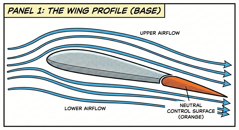
An airplane wing is not a flat plank; it has a carefully designed teardrop shape called an airfoil. This shape forces the air to move in different ways over the upper surface (extrados) and lower surface (intrados). According to Bernoulli's Principle and Newton's Third Law, this difference in air velocity and pressure, along with the downward deflection of airflow, generates an upward force: lift.
Primary flight controls work by temporarily altering the curvature (the "camber") of the airfoil in a specific section of the aircraft.
The Effect of Deflection:
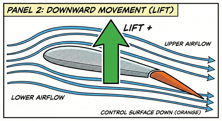
When a control surface (whether aileron, elevator, or rudder) is moved downward:
It increases the effective camber of that section of the wing or stabilizer.
It increases the relative angle of attack at that point.
The result is a significant increase in lift generated on that specific surface.
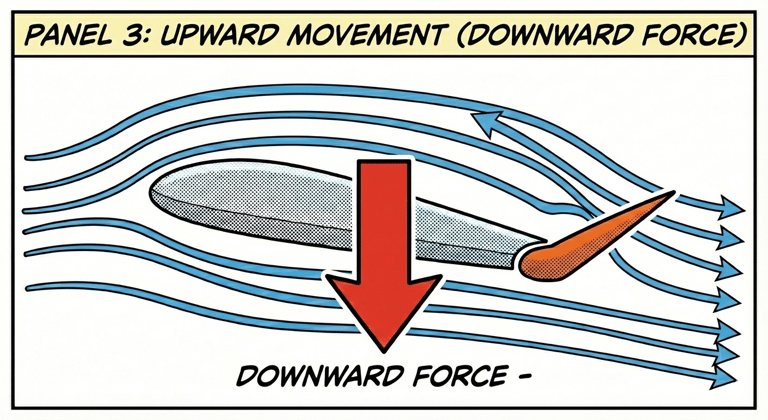
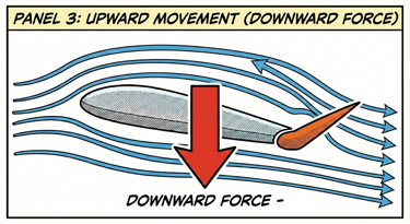
When the surface is moved upward:
It decreases camber (or creates negative camber).
It decreases the angle of attack.
The result is a decrease in lift (or creation of negative lift/downward force).
Applying Physics to Movement:
Let's revisit the roll. The pilot moves the yoke left. The right aileron moves down, increasing camber and lift on the right wing. The left aileron moves up, decreasing lift on the left wing. This difference in force (more lift on one side, less on the other) creates a powerful torque that rotates the aircraft.
The same principle applies to the elevator. Pulling the yoke back raises the elevator. This "spoils" the lift on the tail, creating a downward force. Since the tail is a long lever, this force pushes the tail down, and pivoting on the CG, the nose rises.
It is a delicate dance of force management. Pilots are not just "turning" the plane; they are constantly reshaping the aircraft in mid-flight to manage the distribution of air pressure around it.
Conclusion
Primary flight controls are the essential interface between human will and aerodynamic reality. Whether operated by tensioned steel cables or light-speed digital impulses, their function remains the same: to give the pilot the ability to command rotation in three spatial axes. Understanding these systems is not just for engineers or pilots; it is the key to appreciating the incredible complexity and controlled beauty of human flight. The next time you board a plane, remember the small surfaces on the wings and tail that will work tirelessly to carry you safely to your destination.
Did you enjoy it?
Spread the word


Contact
Fale conosco para mais informações.
© 2025. All rights reserved.
About me